- All
- Product Name
- Product Keyword
- Product Model
- Product Summary
- Product Description
- Multi Field Search

 |

loading


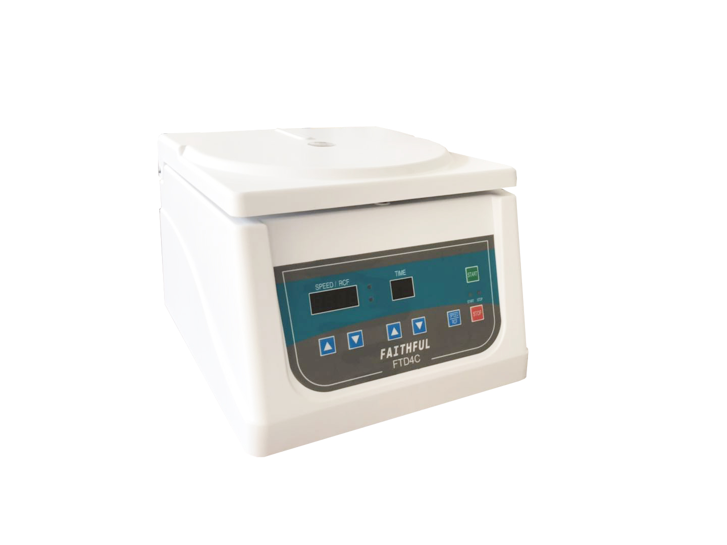
FTD4C
FAITHFUL
Technical Parameter
Maxinnum running speed: 4000r/min
Maximum centrifugal: 2350Xg
Rotor capacity for maximum speed: 12 × 15ml
Maximum capacity: 12 × 15ml
Rotor speed for maximum capacity: 4000r/min
Noise: ≤55dB
Power supply: AC220V 50Hz 5A
Relative humidity: ≤85%
Ambient temp: 5℃~30℃
Overall dimension: 270 × 290 × 230mm
Packing size:350 × 340 × 360mm
N.W/G.W(kg):8/9
Main Construction and Feature
The centrifuge consists of carcass, driving component, rotor, electric control component, and refrigerating component of compressor unit etc. It is driven directly by direct current brushless motor, and made damped vibration attenuation with special dampener, there for which is of small vibration and low noise, and is of high control precision of rotating speed and time with module control.
Mating Rotor
Mating rotor table
( Please order otherwise when user has special requirement. )
Model | Name | Maxi.speed (r/min) | Maxi. centrifugal | Maxi.capacity | Remarks |
NO.1 | Angular rotor | 4000 | 2350Xg | 12×15ml | -- |
The rotor of the machine is mated according to order requiretnent and
operated according to set parameter.
InstaIIation Requirement
1.Installing position should select the strong flat and prevent the influence of external vibration to the machine.
2.Prevent the sunlight from direct irradiation. Indoor should be siccity and cleaning
3.Distance iörm the machine to wall should be more than
4.Installing rotor. and Inaking location and fastening.
5.Power supply should be one-way 22V.
Electric Plug capacity should be no less than Individual earth wire should be firmly connected.
panel of control box
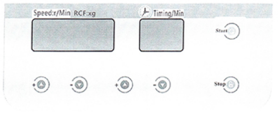
Fig.1 Control Panel
1.1 Open gate cap and install rotor.
1.2 Centrifugal pipe and pipe carrier after adding in sample are placed
symmetrically in the rotor.
1.3 Press swith of power supply after shutting off gate cap.
1.4 Speed display the button below, Press the "+" or "-" adjustment speed parameter, speed setting range: 0~4000 r/min
1.5 Time display the button below. Press the "+" or "-" adjustment centrifuge elapsed time, time setting range: 0~99 r/min
1.6 Press stop key to stop the machine operation. Gate cap can only opened when speed is reduced to zero(o). First of all, Press the white button ,On the left side of the top. Hold down the white button. the door with the hand cover open up.
1.7 Fetch sample to prepare for next separation.Repeat above mentioned operation process.
1.8 Shut off power supply after finishing test.
1.9 During Power fåilure. pull of open gate cap below the instrument in rotor running stopping completely and no risk to open gate.
2 Driving system use direct driving of brushless motor with sealing prelubricated driving shaft, and special vibration damper greatly reduces vibration and noise. Note: It appears that produces sotne vibration under critical speed (roughly between 400r/min and 900r/min) . This vibration is a normal phenomenon. Unbalanced detector sends the motor to stop running when producing abnormal vibration.
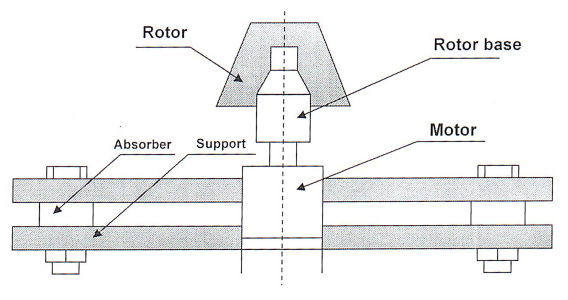
Fig.2 Drive mechanism
Electric control system
Electric control system states microcomputer controlling for speed, temperature and centrifugal time. Speed and temperature are displayed with numerical code. The centrifugal is displayed according to different rotors, and stated at the same time.
Safe protective device
Overspeed protective device
Motor generates automatically power-off when speed is out of control or exceeds 500r/min to prevent overspeed running of the machine so that protecting safety of the machine and personnel.
Unbalance protective device
Owing to unbalance running, the machine produces the vibration. Faullamp lights, then motor is power off and the machine stops running when amplitulde exceeds provided value.
Maintenance
Painting a few grease or lubricating-oil to prevent rusting and easy to
install and remove the rotor.
Conduct mgtllar cheek whether the rotor is of the erosion and
haircrack. Check before use is a more important. Pay attention to renewal of the centrifugal tube.
When the rotor is not used over a long period of time, place it in dry
-ing place without erosion to prevent the erosion to prvvent the erosion and rusting.
Quality Guarantee Period for the rotor
Rotor installation
Clean the rotor base in the centrifügal chamber and the bore of the rotor body with clean flannelette and paint thin grease. and lift the rotor with hands and place on the rotor base in the centrifugal chamber, Rotor boreis inserted firmly on the rotor base and screw down with bolt.
Proper use of the rotor
The rotor should conduct the use and running according to stated speed.
Clean the centrifugal cup before use and place the test solution after weighing in the centrifugal cup. Weighing error of the test solution is less than If the centrifugal test sample is few. then divide the test solution into a half or one fourth on the average. and place symrnetrically test solution after weighing in the centrifugal cup. and fill the water or other solution in the rest empty cups and place them symmetrically after symmetrically after weighing. The centrifugal cup running must be in the same time for every running. Strictly forbid the centrifuge running when the centrifugal cup or test solution is unsynmetrically placed. Abnortnal use of the centrifugal cup may produce strong vibration and even datuage the machine and
danger staff sale.
Maintenance of the rotor
Check regularly the oxidation layer of the inside and outside face of
the rotor and the centrifugal cup. If there exist the peeling. erosion, critical sculling or haircrack.then should stop to use.
Clean the residual liquid or water of the inside and outside face of the rotor and the centrifugal cup with clean flanneled. and dry by airing for stand-by application after completion centrifugal work.
Prevent the rotor come into collision with the centrifugal cup each other when application rotor and centritilgal cup.
Need not to use the rotor and the centrifugal cup should be take out from the centrifugal chamber and place in dry place.
Attention matters for safe operation
Take out the foreign matter from the cavity of the centrifugal chamber before use centrifuge.
Strictly forbid that running speed of the rotor exceeding rated speed.
Strictly forbid unbalance running.
The rotor should be installed firmly on the rotor base.
Strictly forbid to open the cap of the centrifugal chamber when the centrifuge is running.
Strictly forbid to touch the rotor in running with hand.
Strictly forbid to high-speed running without the rotor.
Various rotors matched for the machine are of operating life up to five (5) years i.e quality guarantee period of the rotors are of five years.
Quality guarantee period of the rotor is calculated from the day to leave factory. tched rotor can produce corrosion spot and crack in low-speed state. There for rictly forbid to use the rotor with the erosion and crack. Guarantee period of the tor is not suited for etched and split rotor.
panel of control box
Fig.1 Control Panel
1.1 Open gate cap and install rotor.
1.2 Centrifugal pipe and pipe carrier after adding in sample are placed
symmetrically in the rotor.
1.3 Press swith of power supply after shutting off gate cap.
1.4 Speed display the button below, Press the "+" or "-" adjustment speed parameter, speed setting range: 0~4000 r/min
1.5 Time display the button below. Press the "+" or "-" adjustment centrifuge elapsed time, time setting range: 0~99 r/min
1.6 Press stop key to stop the machine operation. Gate cap can only opened when speed is reduced to zero(o). First of all, Press the white button ,On the left side of the top. Hold down the white button. the door with the hand cover open up.
1.7 Fetch sample to prepare for next separation.Repeat above mentioned operation process.
1.8 Shut off power supply after finishing test.
1.9 During Power fåilure. pull of open gate cap below the instrument in rotor running stopping completely and no risk to open gate.
2 Driving system use direct driving of brushless motor with sealing prelubricated driving shaft, and special vibration damper greatly reduces vibration and noise. Note: It appears that produces sotne vibration under critical speed (roughly between 400r/min and 900r/min) . This vibration is a normal phenomenon. Unbalanced detector sends the motor to stop running when producing abnormal vibration.
Fig.2 Drive mechanism
Electric control system
Electric control system states microcomputer controlling for speed, temperature and centrifugal time. Speed and temperature are displayed with numerical code. The centrifugal is displayed according to different rotors, and stated at the same time.
Safe protective device
Overspeed protective device
Motor generates automatically power-off when speed is out of control or exceeds 500r/min to prevent overspeed running of the machine so that protecting safety of the machine and personnel.
Unbalance protective device
Owing to unbalance running, the machine produces the vibration. Faullamp lights, then motor is power off and the machine stops running when amplitulde exceeds provided value.
Maintenance
Painting a few grease or lubricating-oil to prevent rusting and easy to
install and remove the rotor.
Conduct mgtllar cheek whether the rotor is of the erosion and
haircrack. Check before use is a more important. Pay attention to renewal of the centrifugal tube.
When the rotor is not used over a long period of time, place it in dry
-ing place without erosion to prevent the erosion to prvvent the erosion and rusting.
Quality Guarantee Period for the rotor
Rotor installation
Clean the rotor base in the centrifügal chamber and the bore of the rotor body with clean flannelette and paint thin grease. and lift the rotor with hands and place on the rotor base in the centrifugal chamber, Rotor boreis inserted firmly on the rotor base and screw down with bolt.
Proper use of the rotor
The rotor should conduct the use and running according to stated speed.
Clean the centrifugal cup before use and place the test solution after weighing in the centrifugal cup. Weighing error of the test solution is less than If the centrifugal test sample is few. then divide the test solution into a half or one fourth on the average. and place symrnetrically test solution after weighing in the centrifugal cup. and fill the water or other solution in the rest empty cups and place them symmetrically after symmetrically after weighing. The centrifugal cup running must be in the same time for every running. Strictly forbid the centrifuge running when the centrifugal cup or test solution is unsynmetrically placed. Abnortnal use of the centrifugal cup may produce strong vibration and even datuage the machine and
danger staff sale.
Maintenance of the rotor
Check regularly the oxidation layer of the inside and outside face of
the rotor and the centrifugal cup. If there exist the peeling. erosion, critical sculling or haircrack.then should stop to use.
Clean the residual liquid or water of the inside and outside face of the rotor and the centrifugal cup with clean flanneled. and dry by airing for stand-by application after completion centrifugal work.
Prevent the rotor come into collision with the centrifugal cup each other when application rotor and centritilgal cup.
Need not to use the rotor and the centrifugal cup should be take out from the centrifugal chamber and place in dry place.
Attention matters for safe operation
Take out the foreign matter from the cavity of the centrifugal chamber before use centrifuge.
Strictly forbid that running speed of the rotor exceeding rated speed.
Strictly forbid unbalance running.
The rotor should be installed firmly on the rotor base.
Strictly forbid to open the cap of the centrifugal chamber when the centrifuge is running.
Strictly forbid to touch the rotor in running with hand.
Strictly forbid to high-speed running without the rotor.
Various rotors matched for the machine are of operating life up to five (5) years i.e quality guarantee period of the rotors are of five years.
Quality guarantee period of the rotor is calculated from the day to leave factory. tched rotor can produce corrosion spot and crack in low-speed state. There for rictly forbid to use the rotor with the erosion and crack. Guarantee period of the tor is not suited for etched and split rotor.
Fault | Fault Type | Cheek and treatment | Remarks |
E-1 | Unbalance | Check if centrifugal sample is balanced | Require specially setting |
E-2 | Overapeed | a.Check set speed. b.Check the signal of speed measuring. c.lnform manufacturer. | |
E-3 | Gate cap fault | a. Check if the gate cap is covered firmly. b.Check if the gate cap switch is OK. | |
E-4 | Gate cap opening running | Cover gate cap and restart.
| |
E-5 | Mistaken rotor model setting | Check if the rotor model Corresponds with rotor speed.
| |
E-6 | Mistaken program setting | ||
E-7 | No speed | Cheek if speed input socket is loosened.
|
冀ICP备18005191号 | Copyright © 2018 Faithful Instrument (Hebei) Co.,Ltd. All rights reserved.